
Butterfly valves are a cost-effective and efficient solution for on-off or modulating services. With a lightweight design, small installation footprint, and quick operation, they offer large orifice sizes and a disk that rotates to allow fluid flow. Understanding how butterfly valves work and their applications can help in selecting the right valve for different uses.
How Butterfly Valve Work
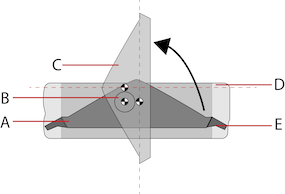
Butterfly valves have a simple design with the main components being the body, seal, disc, and stem as shown in Figure 2. The disc is aligned with the center of the connected piping and connected to an actuator or handle via the stem. When the valve is closed, the disc is perpendicular to the flow and seals against the valve seat. An o-ring in the stem packing prevents leakage. Rotation of the stem by 90° using the actuator or handle causes the disc to also rotate by 90° to become parallel to the flow, allowing for throttling or proportional flow control.

Butterfly valves used in modulating services can be designed with either a linear or equal percentage characteristic.
Linear: A linear characteristic refers to the relationship between the valve opening and the corresponding flow rate, where the flow rate increases linearly as the valve opens. For instance, if the valve is opened by 30 degrees, or one-third of a turn, the flow rate will be 33.3% of the maximum flow rate.
Equal: Equal percentage characteristic means that there is a logarithmic correlation between the disc’s movement and the flow rate. For instance, if rotating the disc by 10 degrees increases the flow rate by 70% (from 100 to 170 m3/h), the next 10 degrees rotation will also increase the flow rate by 70% (from 170 to 289 m3/h). Some advanced butterfly valves can maintain this correlation over a wider range, from 20 to 90 degrees when fully open.
The symbol for a butterfly valve is shown below:

Types of Butterfly Valves
There are different designs of butterfly valves that cater to specific pressure ranges and applications. These valves can be classified based on their disc closure design, connection design, and actuation method.
Disc closure design
The location of the stem in relation to the disc’s centerline and the surface angle of the valve seat determine whether butterfly valves are concentric or eccentric.
Concentric
A centric or concentric butterfly valve represents the most fundamental design, in which the stem passes through the centerline of the disc, and the seat is the inner diameter periphery of the valve body (Figure 4 on the left). The valve design is known as resilient-seated since the flexibility of the rubber seat is essential for effective sealing. During a 90° rotation, the disc contacts the seat at around 85° while closing. Concentric butterfly valves have applicability in low-pressure ranges.
Eccentric
Figure 4 shows a centric or concentric butterfly valve, which is the most basic design. In this design, the stem passes through the centerline of the disc, and the seat is the inside diameter periphery of the valve body (left side of Figure 4). This design is called resilient-seated, as the efficient sealing relies on the flexibility of the rubber seat. The valve closes when the disc first comes into contact with the seat at around 85° during a 90° rotation. Centric butterfly valves are suitable for low-pressure ranges.
On the other hand, an eccentric butterfly valve has a stem that is not aligned with the centerline of the disc but located behind it (opposite of the flow direction) as shown in Figure 4 (right side). In a single offset butterfly valve, the stem is directly behind the disc’s centerline, reducing the contact between the disc and the seal before the valve is fully closed. This design enhances the service life of the valve.
Double offset or doubly eccentric butterfly valves have a stem that is behind the disc’s centerline and has an additional offset to one side, as shown in Figure 5. The double eccentricity design of the stem reduces the contact between the disc and the seat to the last 1-3° of disc closure.
In contrast, a triple offset butterfly valve (TOV or TOBV) has a similar design to a double offset butterfly valve, with an additional offset on the disc-seat contact axis. The seat surface has a conical shape, coupled with the same shape at the ridge of the disc, minimizing the contact before full closure of the valve. A triple offset butterfly valve is highly efficient, experiences less wear, and is suitable for critical applications. These valves are often made of metal seats for a bubble-tight shut-off and are suitable for higher temperature ranges.
Finally, high-performance butterfly valves use the pressure in the pipeline to increase the seal between the seat and the disc edge. These butterfly valves have higher pressure ratings and are less prone to wear.
Connection Design
Different connection types are available for butterfly valves to connect to a piping system. Among them, the most commonly used ones are wafer type, lug type, and flange.

Wafer-style
A wafer-style butterfly valve is a cost-effective version that is sandwiched between two pipe flanges, and long bolts that cross the entire valve body connect the pipe flanges. This valve type is suitable for preventing backflow in systems designed for universal flow and sealing against bi-directional differential pressures. Some versions of this valve have flange holes outside the valve body (Figure 6 labeled A), and efficient sealing is achieved through the combination of gaskets, o-rings, and flat valve faces on both sides of the valve.
Lug-Style
In a lug-style butterfly valve, threaded inserts or lugs are present outside the valve body (as shown in Figure 6 labeled C). Both sides of the bolt inserts connect pipe flanges using two sets of bolts, without nuts. This design allows for one side to be disconnected without impacting the other’s function in dead-end service. However, lug-style butterfly valves have a lower pressure rating when used in dead-end service, and unlike wafer butterfly valves, they support the weight of the piping through the valve body.
Actuation method
There are various ways to actuate butterfly valves, including manual operation using handles or gears and automatic operation using electric, pneumatic, or hydraulic actuators. These devices allow for precise disc rotation from fully open to fully closed positions. Below is a brief description of the different types of actuation methods available.
Manual butterfly valve
Two common methods of manually actuated butterfly valves are:
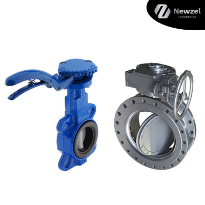
Lever Handle::Small butterfly valves are often manually actuated using a hand lever that allows the valve to be locked in an open, partially open, or closed position. Figure 4 (left) shows an example of this type of valve. For larger valves that are located underground or within a pit, extended spindle butterfly valves with long stems are used to enable remote operation.
Gear Box: Gear-operated butterfly valves are designed for slightly larger valves and they utilize a gearbox to increase torque, but this comes at the expense of decreased speed of opening/closing. These valves are also self-locking, meaning they cannot be back-driven, and they can be equipped with position indicators. Figure 4 (right) shows an example of a gear-operated butterfly valve.

Actuated butterfly valve
Power-operated actuators offer a dependable way to remotely control butterfly valves. They make it possible to rapidly operate larger valves. These actuators can be designed to stay open in case of actuator failure (fail-open) or remain closed in case of actuator failure (fail-close). Additionally, they often come equipped with a manual actuation method in case of failure. There are three types of automatic actuators, which are described below:
- Electric actuators: These utilize electric power to operate the valve, and the control signal can be wired or wireless. They are suitable for use in hazardous environments since there is no fluid leakage or emissions.
- Pneumatic actuators: These utilize compressed air to operate the valve and are commonly used in industrial settings where compressed air is readily available. They are reliable, durable, and require minimal maintenance.
- Hydraulic actuators: These utilize hydraulic fluid to operate the valve and are suitable for high-pressure applications. They are often used in the oil and gas industry and require specialized training and maintenance.
ISO standards for actuated butterfly valves
ISO (International Organization for Standardization) has established several standards for actuated butterfly valves. The two most common standards are ISO 5211 and ISO 5752.
ISO 5211 specifies the dimensions and tolerances for the attachment of valve actuators to industrial valves, including butterfly valves. This standard defines the dimensions of the valve actuator mounting flange and the dimensions of the valve stem end connection.
ISO 5752 specifies the face-to-face and center-to-face dimensions for butterfly valves. This standard also provides information on materials, pressure-temperature ratings, and testing requirements for butterfly valves. The standard includes design criteria for concentric, double offset, and triple offset butterfly valves.
Butterfly valve wiring
When a butterfly valve is actuated electrically, it can be wired in two different ways:
2-point control actuators: There are three wires: +, -, and a control wire. To open the valve, the control wire needs to be powered, and to close the valve, the control wire needs to be unpowered, or vice versa. This function is particularly useful if the valve is located remotely. If no power is supplied to the entire unit, the valve remains in its latest position.
3-point control actuators: There are four wires, two of which are control wires, and the other two are for + and -. The actuator can be opened or closed depending on which control wire is powered. This method allows for intermediate stops or partially open positions. However, it is important to note that both control wires should not be activated simultaneously as this may cause damage to the actuator.
Butterfly valves Applications
Butterfly valves have a wide range of applications in various industries such as pharmaceuticals, chemicals, oil and gas, food processing, water and wastewater treatment, fire protection, fuel handling, gas supply, and sanitary fittings. In water supply systems, butterfly valves are used as control valves to regulate and shut off water flow. These valves are available in large sizes and can handle liquids with relatively high amounts of solids at low pressures. For corrosive and marine environments, stainless steel butterfly valves are preferred due to their high durability and resistance to corrosion.
Conclusion
Butterfly valves are a versatile and reliable solution for controlling the flow of fluids in various industries and applications. They come in different types such as wafer, lug, and flange connections and can be operated manually or automatically using different actuation methods such as electric, pneumatic, and hydraulic. ISO standards ensure the quality and performance of actuated butterfly valves. Electrical actuation can be achieved using either 2-point or 3-point control actuators with different wiring configurations. Butterfly valves are available in different materials, sizes, and designs to suit different environments and applications.
