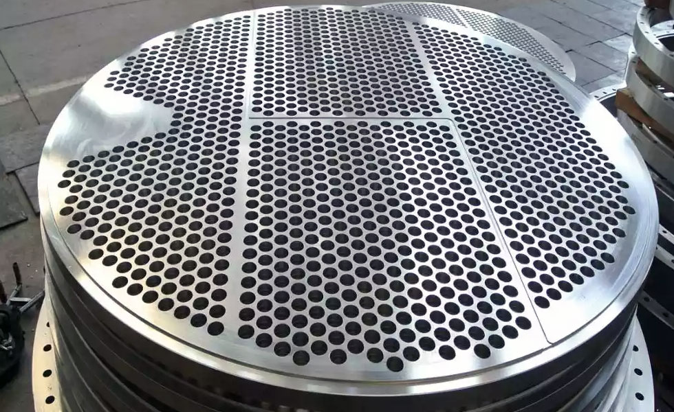
Baffles are flow-directing or obstructing vanes or panels used to direct a flow of liquid or gas. It is used in some household stoves and in some industrial process vessels (tanks), such as shell and tube heat exchangers, chemical reactors, and static mixers. Baffles are an integral part of the shell and tube heat exchanger design. A baffle is designed to support tube bundles and direct the flow of fluids for maximum efficiency.
Baffle design and tolerances for heat exchangers are discussed in the standards of the Tubular Exchanger Manufacturers Association. There are many different sizes and forms of baffle configurations. The most popular is a segmented circle-shaped perforated plate. The segmental baffles are positioned along a bundle of tubes at predefined intervals so that the segmented section faces are in opposition to one another. Baffle plates made of stainless steel are a crucial part of shell and tube heat exchanger designs. A baffle plate is made to guide the fluid flow and stiffen tube bundles for maximum effectiveness.
Baffle plates are often used in boilers, reservoirs, hydraulic tanks, pressure vessels, wood burners, steam turbines, large central air conditioning units, etc.
Use of Baffle Plates
- Hold the tubes in position (preventing sagging), both in production and operation.
- Prevent the effects of steam starvation.
- Direct shell-side fluid flow along the tube field increases fluid velocity and the effective heat transfer coefficient of the exchanger.
- A static mixer is used to minimize the tangential component of velocity.
- In a chemical reactor, they are attached to the interior walls to promote mixing.
- Household stoves
Types of Baffles:
- Segmental baffles
A plate-type baffle may be single segmental, double segmental, or triple segmental. Single and double segmental baffles are most frequently used as they divert the flow most effectively across the tubes.
- Disk and Doughnut Baffles
It has alternating outer rings and inner disks which direct the flow radially across the tube field. They are all very effective in converting pressure drop to heat transfer conversion.
- Orifice baffles
In this type of baffle, the shell side fluid follows through the clearance between the tube outside diameter and the baffle hole diameter.
- Rod baffles
This type is made of metal rods rather than plate metal baffles. This type is used wherever a very low-pressure drop is required. Rod baffles also eliminate the tube vibrations that occur with plate baffles when fluid velocities are high.
The flow on the shell side is mainly parallel to the tube axis. The tubes are arranged with a square pitch. Rods, with a diameter equal to the clearance between the tube rows, are attached to ring supports and placed between alternate tubes in both horizontal and vertical directions. The normal rod diameter is 6.35 mm (0.25 inches), and each tube is supported on all four sides at several points along the exchanger. Rod baffles are mainly used when the pressure drop available is very low or there is a pressure drop issue.
What is a Baffle Cut?
This term, which is defined as the height of the segment that is cut in each baffle to allow the shell side fluid to flow across the baffle, is typically stated as a percentage of the inside diameter of the shell that is not covered by the baffle.
The standard recommended value of 20 to 25 percent shell diameter cut is used in the design of shell and tube heat exchangers; the larger the cut, the lower the pressure drop; however, this has an adverse effect on heat transfer because the poorly distributed flow with large eddies is produced, causing stagnant areas or dead spaces behind the shell’s baffles, which results in a lower heat transfer coefficient. The pressure drop and heat transfer coefficient are both larger with a smaller cut.
For single segmental baffles, the maximum cut is 45 percent. The baffle cut direction can be horizontal or vertical and ranges from 15 to 45 percent of the shell interior diameter. Bad designs usually come from lowering the baffle cut below 20% to increase the heat transfer coefficient on the shell side or raising the baffle cut above 35% to reduce the pressure drop on the shell side.
Some solutions, such as twin segmental baffles, split shell flow using a TEMA J type shell, or cross flow shell using a TEMA X type, can be utilized to lower the pressure drop in the shell side without increasing the baffle cut over 35%.
What is Baffle to Tube Clearance?
There is a space between the outside diameter of each tube and the diameter of the baffle hole. The tubes may easily be placed into the baffle thanks to this clearance. The clearance optimal requirement values provided by TEMA standards are used in the industry. These specifications take into account the necessary space for the baffle plate and tube’s differential expansion and contraction. To eliminate stagnant areas, make turbulent conditions more consistent, and lessen shell side pressure drop, a certain amount of leakage through the clearances is tolerated. Leakage also lessens deposits in regions where water is stagnant. Large clearances may result in excessive fluid bypassing, which could leave areas of the shell with low fluid velocities and a lack of fluid.
Newzel Industries deals in all types of Baffle plates apart from other steel equipment. We deliver our products worldwide. By incorporating new-age technology and innovation we aim to exemplify the passion in our work and service to our customers. We are involved with every phase of the seamless pipe manufacturing process and we offer a wide range of services for our clients.
For more information, contact us!
