
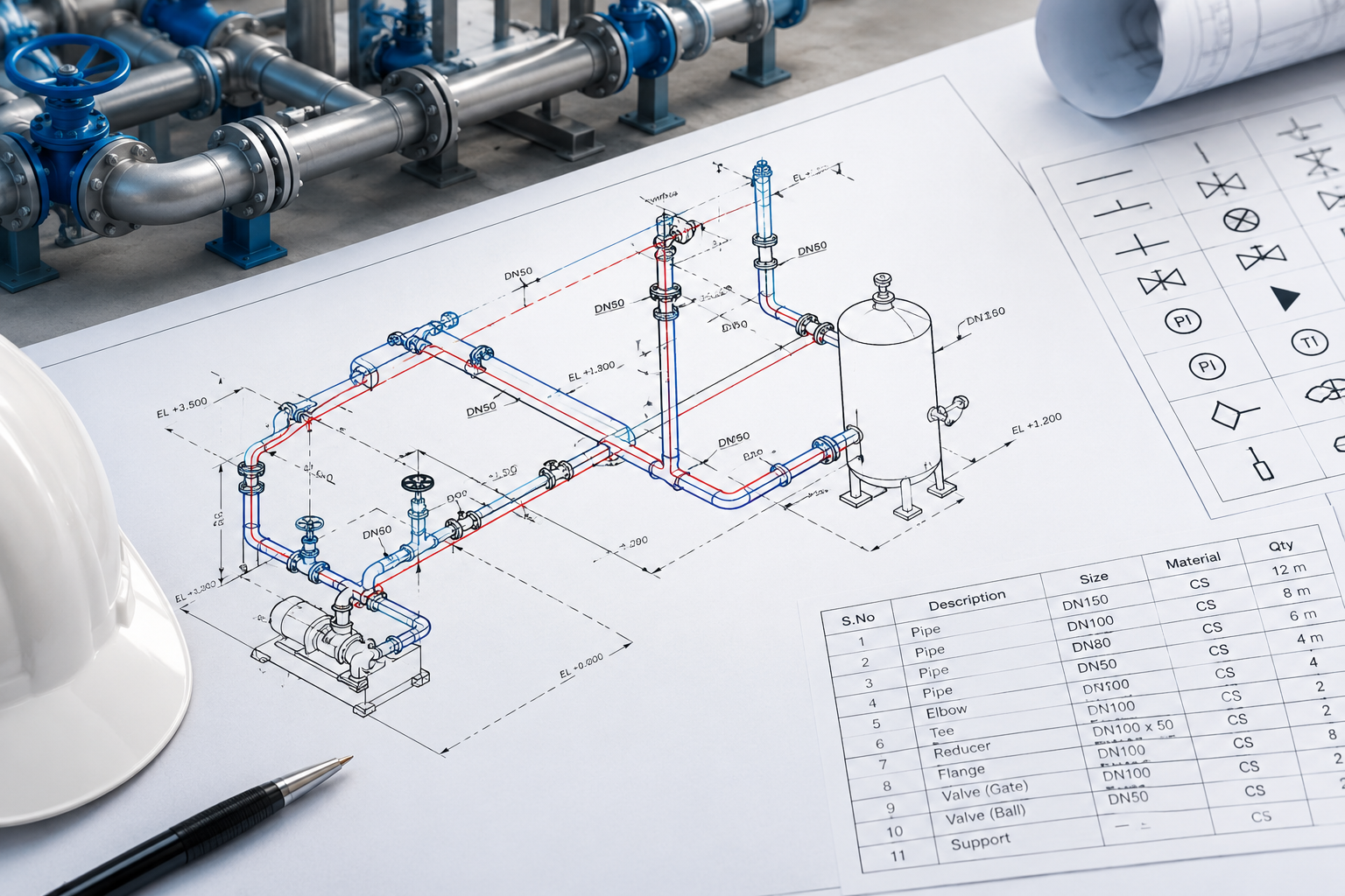
A piping isometric drawing is a three-dimensional representation of a single pipe line that is made on an isometric grid rather than to scale. This drawing comprises pipe lines, measurements, fittings, welds, and a bill of materials (BOM). This guide will cover the components of a piping isometric drawing, the meanings of commonly used symbols, reading line numbers and spool numbers, and how to prepare a bill of material with an example bill of material. The shop-floor mistake notes are based on Newzel Industries fabrication of pipe spools versus client isometrics.
What is Piping Isometric Drawings?
A piping isometric drawing, also known as an isometric piping drawing, depicts a pipeline running from one terminal point to another. It is depicted isometrically, which means that the pipe is portrayed as if viewed from a corner, with the length, breadth, and height all represented in the same design. The drawing is not to scale. This is an eye-catcher for beginners for a reason: if there are too many fittings in a cramped location, it will be difficult to read if drawn to scale. The drafter separates the pieces so that they may be read, and the written dimensions reflect the real lengths. Read the numbers; don’t use a ruler to measure the line. Most isometrics for major projects are generated automatically from a 3D plant model. Hand-drawn or rudimentary CAD isometrics are still widely utilized for modest tasks, repairs, and field adjustments.
Comparison of isometric, P&ID, and general arrangement drawings
These three drawings are sometimes mistaken. Each solves a unique question for a different team.
| Document Type | Shows | Scale | Used By |
| P&ID | Process flow, equipment, instruments, control logic | Not to scale | Process and instrument engineers |
| Piping GA / Plan | Plan and elevation layout of equipment and pipe | To scale | Piping designers, civil and site teams |
| Piping Isometric | One line routing with exact dimensions and components | Not to scale | Fabricators, welders, inspectors, procurement |
| Document Type | Shows | Scale | Used By |
In a nutshell, the P&ID tells you what the process requires, the GA tells you where items are in the plant, and the isometric shows you exactly how to construct one line.
Why Piping Isometrics Are Important for Fabrication and Procurement.
The isometric is the document that connects design, workshop, and buy desk. Four teams rely on it.
Material take-off: Each pipe length, fitting, flange, bolt, and gasket is tallied from the isometric and recorded in the BOM.
Shop fabrication: spools are cut, fitted, and welded using isometric dimensions and weld markings.
Inspection: Weld numbers and NDT criteria are traceable back to the drawing, making the inspection record auditable.
Tie-in locations, field welds, and routing annotations help installation personnel.
A BOM line that conflicts with the pipe class is a common cause of rework. A flange ordered one grade lower than the line’s pipe class is only detected when the spool reaches inspection, following cutting and welding.
Anatomy of an isometric: title block, drawing body, and BOM area.
Most isometrics have a similar layout, even if corporations format them differently.
Title block includes the drawing number, line number, pipe class, design pressure and temperature, from and to points, revisions, and approvals.
The drawing body includes the pipe path, components, measurements, elevations, and annotations.
The BOM area is normally toward the bottom or on the right side, with each item listed by number.
Orientation: a north arrow or direction indication, usually at the top, so the pipe can be aligned with the plot plan.
Understanding the Isometric Grid: Offsets and Directions
On an isometric grid, one axis is vertical and the other two are at 30 degrees from the horizontal. This sets the three axs 120 degrees apart. This is frequently referred to as a “60-degree” angle, which is the angle measured in the opposite direction between each sloping axis and the vertical line. Both descriptions refer to the same grid. Vertical pipe travels directly up and down, while horizontal pipe in the two plan directions follows the two sloping lines.
Types of Offsets
Not every pipe follows the three primary axes. A pipe that alters position is known as an offset, and isometrics depict three types:
Vertical offset: the pipe moves up or down while remaining in a single vertical plane.
Horizontal offset means that the pipe slides sideways in the horizontal plane.
Combined (rolling) offset: the pipe moves in more than one direction at the same time, with a little right angle triangle on the design indicating the travel in each direction.
Elevations and Slope
Elevation callouts, denoted by EL followed by a height, indicate the level of the pipe centerline above a datum. Slope annotations indicate where the pipe must descend in a specific direction, for example, for drainage.
Piping Isometric Symbols and Their Meaning
Symbols are shorthand for isometric. The table below lists the ones you will encounter the most frequently. Symbol norms differ per firm and project, so always refer to the legend on the drawing you are working from.
| Item | How it appears on the isometric | What to note |
| Pipe run | Single line along the isometric axes | The line is the centreline. Dimensions give the real length. |
| 90 and 45 degree elbow | Bend drawn on the line at the change of direction | Long radius unless noted. Type and grade go in the BOM. |
| Tee and branch | Line splitting off the run | Equal or reducing tee is decided in the BOM. |
| Reducer (concentric or eccentric) | Tapered symbol between two sizes | Eccentric reducers need the flat side (top or bottom) noted. |
| Flange | Short bar or double line across the pipe | Type (weld neck, slip-on, blind), face and rating go in the BOM. |
| Valve (gate, globe, ball, check) | Distinct symbol per valve type on the line | Handwheel or actuator direction is shown where it matters. |
| Olet or branch connection | Small fitting on the run for a branch | Type such as weldolet or sockolet is in the BOM. |
| Cap | Closed end symbol | Used at dead ends. |
| Shop weld | Solid dot on the line | Weld is made in the fabrication shop. |
| Field weld | Dot with a flag or similar marker | Weld is made on site. |
| Flow arrow | Arrow next to the line | Shows direction of flow. |
| Support, guide, anchor | Callout with a support tag | Detail is on a separate support drawing. |
| Continuation or match line | Dashed line with a drawing reference | Links to the next sheet of the same line. |
| Spec break | Note at the point where pipe class changes | Material or rating changes at this point. |
| North arrow | Arrow with N at the top of the sheet | Keeps the orientation correct. |
| Vent / drain | Small branch at a high or low point, ending in a valve or cap | Size and end type go in the BOM. |
| Instrument connection | Small branch labelled with the instrument tag | The tag refers back to the P&ID. |
Several of these warrant a deeper study. Fittings like elbows, tees, and reducers are often buttweld fittings on bigger lines, and the drawing just indicates their position, but the BOM includes their size, schedule, and grades. Flanges work similarly: the drawing shows where the flange is located, and the BOM specifies whether it is a weld neck flange, a slip-on, or a blind, as well as the face and rating.
Weld symbols are just as important. The difference between a shop weld and a field weld determines what is done in the workshop and what is left for the job site, as well as spool length and transportation. If you want to learn more about how the weld type affects the joint, check out our comparison of socket weld vs butt weld connections.
Reading Line Numbers, Spool Numbers, and Pipe Classes
Line number
Every pipeline has a unique line number, and it typically condenses numerous facts into a single string. We created the following example for illustration: 6-PW-1024-A1A.
The nominal pipe size is 6″.
The service code is PW, which stands for process water.
The sequence number for this line is 1024.
A1A represents the pipe class.
Companies use different forms for line numbers, therefore check the project’s line list to confirm the format.
The spool number
Long lines are rarely constructed or transported as a single unit. It is cut into spools, which are portions that are suitable for manufacture and transportation, and then joined on-site at the field welds. Each spool is assigned its own number, for example, 1024-SP01, 1024-SP02, and so on. The spool number allows the shop, inspector, and site crew to refer to the exact same component. For the material side, check out our stainless steel products.
The Pipe Class
The pipe class is essential to the material. It refers to a pipeline specification that specifies the pipe material and grade, wall thickness, flange rating, fitting types, gaskets and bolts, and corrosion allowance. If you understand the pipe class, you know what each component on the line must be comprised of. This is also how problems are detected, as anything in the BOM that clashes with the pipe class is incorrect.
What Is the Bill of Materials for Piping Isometric?
The bill of materials is a list of all the components required to construct the line depicted on the isometric. It is created from the drawing during material take-off and is used by both the buyer to place orders and the store to supply material to the business.
Typical BOM columns.
Item number corresponds to the balloon numbers on the illustration.
Quantity or length: The number of pieces or meters of pipe.
Description: Describes the item, such as “90 degree long radius elbow, BW”.
Dimensions: nominal pipe size.
Material and grade: for example, ASTM A106 Gr. B.
Wall thickness schedule, also known as flange class.
End connections include buttweld, socket weld, flanged, and threaded.
Standard: the controlling dimension or material standard.
Item numbers provide the link between the graphic and the list. Each balloon on the isometric corresponds to one row in the BOM, allowing you to always navigate from a fitting on the picture to its entire description.
Related listings.
Some isometrics additionally include a cut pipe list (the length of each pipe piece), a weld list (each weld with its number and kind), and a bend table if bends are required. These reside next to the BOM and are utilized by both the business and the inspector.
BOM versus MTO
The BOM belongs to only one isometric. The material take-off (MTO) sums the BOMs of multiple isometrics to get the total quantity available for purchase. Buyers work from the MTO, whereas fabricators work from the BOMs for each drawing.
Sample BOM
The table below illustrates a 6-inch carbon steel line. Before ordering, always check each value against the project specification and the applicable ASME tables.
| Item | Qty | Description | Size | Material | Rating / Sch. | Standard |
| 1 | 3.2 m | Seamless pipe, beveled ends | 6 in | ASTM A106 Gr B | SCH 40 | ASME B36.10M |
| 2 | 2 | 90 degree long radius elbow, BW | 6 in | ASTM A234 WPB | SCH 40 | ASME B16.9 |
| 3 | 2 | Weld neck flange, raised face | 6 in | ASTM A105 | Class 150 | ASME B16.5 |
| 4 | 1 | Gate valve, flanged | 6 in | Per project spec | Class 150 | Per project spec |
| 5 | 2 | Spiral wound gasket | 6 in | SS 304 / graphite | Class 150 | ASME B16.20 |
| 6 | 16 | Stud bolt with two nuts (8 per joint, 2 joints) | 3/4 in x length per flange stud table | ASTM A193 B7 / A194 2H | Class 150 | Per project spec |
Item 1 is the pipe, in this example an ASTM A106 Gr B pipe. Its dimensions and wall thickness can be verified using a pipe size chart and a pipe schedule chart. For item 3, our guide to flange ratings explains how the Class 150 grade works. Item 6 makes use of nuts that meet the ASTM A194 standard for nuts and bolting. If the line has branches, the BOM includes the branch fittings, such as weldolets.
How Pipe Isometrics Are Created
There are two approaches for producing isometrics. They are prepared with design software such as AutoCAD Plant 3D, AVEVA E3D, or Hexagon Smart 3D, and are then input into isometric software via a Piping Component File (PCF) to ensure consistency in drawings and BOMs for major projects. When creating isometric drawings, making adjustments in the field, or performing repairs on small works, drafters use isometric grid paper or CAD to generate the BOM from the completed drawing. In either scenario, each illustration must be examined for accurate size and component details before being approved and released.
How to Read a Piping Isometric Drawing: Step by Step
Read the title block first, which includes the line number, pipe class, design conditions, from and to points, and revision letter. Stop if the revision is not the most recent one issued.
Find the north arrow and align the drawing with the plot plan.
Trace the line from the beginning to the conclusion of the flow arrow, noting each change in direction, elevation (EL), and specification.
Compare each symbol to the legend, then read the dimensions instead of measuring the lines.
Tie each balloon number to its BOM row and ensure that the material, rating, and end connection are consistent with the pipe class.
Prior to cutting, compare the shop and field weld markings to the spool breakdown.
Common Mistakes in Reading and Preparing Isometrics
Reading dimensions as scaled lengths. The drawings are not to scale.
Ignoring revision letters, work continues on an old drawing.
Skipping notes and the legend, where special requirements are frequently disguised.
Confusing shop and field welds, which alters what is built in the shop.
Conclusion
Most isometric errors are detected by three checks: reading the dimensions rather than measuring the lines, matching every symbol to the legend, and matching every balloon number to a BOM row that corresponds to the pipe class. Understanding plumbing isometric drawings can assist decrease fabrication errors, prevent material mix-ups, and increase installation accuracy. If you’re preparing spools from an existing isometric, send the drawing and BOM to Newzel Industries for review before beginning manufacture.
